
Project Overview:
This project documents the build of a fully electric two-wheeler—driven by the need for a more efficient and independent transportation method, far from the limits of public transit. What began as a modest attempt to electrify an old aluminum-frame bicycle soon evolved into a technical and resourceful engineering effort.
Initial salvage attempts—including repurposing a worn-out bicycle and a scrapyard scooter—were halted due to structural limitations and integration issues. These setbacks led to a new approach: using brand-new, compatible components while maintaining a strict budget.A 64V 54Ah battery pack was built and later paired with a high-output smart BMS to match the demands of a 4kW peak BLDC motor.
Spot welding the battery cells posed another challenge, prompting a creative solution. An unused industrial spot welder in the workshop was reengineered to safely weld battery tabs, despite originally being designed for metalwork.
This page documents each stage of the process—from setbacks to solutions—with insights, images, and updates.
The project is ongoing. Further developments will be shared here!
Some background information about this project of mine:
Here’s the thing: I live far from the city center and have always longed for a better transportation alternative to public transit. Before the accident, I regularly rode my bicycle to the city center, to my math lessons, my voluntary teaching sessions at the Municipality’s Children’s Rights Unit, and many other places.
One day, while wandering in the basement, I came across my 9-year-old bicycle. It struck me—what if the power source wasn’t the rider, but a battery? That was the moment the journey began. Given the bicycle’s small aerodynamic footprint, I believed that if I integrated a battery, a motor, and a control unit, it could work seamlessly.
But oh, how wrong I was...

Image 1: The bicycle I initially intended to salvage.
Due to a series of technical challenges—including, but not limited to:
- The bike being made of aluminum (a soft and costly material that is notoriously difficult to weld),
- Limited space for integrating a battery pack and gear system (as explained later on this page),
- The structural limitations of the stock wheels,
I decided to shift my focus and began searching for a motorcycle in nearby scrapyards. It wasn’t long before I came across a wrecked motorcycle—most likely previously used by a delivery rider.

Image 2: Front assembly of the scrapyard scooter.

Image 3: Rear wheel of the scrapyard scooter.
After a few days of tinkering, I came to two realizations:
1- The vehicle I had found was actually a scooter, not a motorcycle.
2- I couldn’t mount its wheels to a powertrain.
The main obstacle was that the rear wheel was originally connected
directly to a combined gearbox-motor assembly. Additionally, welding it to a
mounting rod wasn’t an option, as the wheels were made of aluminum.
Due to these complications, I decided to sell the entire assembly back to the scrapyard.

Image 4: Components required for connecting the rear wheel assembly.
Second Stage: Brand New Parts
Following these two unsuccessful salvaging attempts, I decided to purchase brand-new and fully compatible parts. Through negotiation, I managed to reduce the total cost by roughly 35%.

Image 5: Brand-new wheel and shock absorber set.
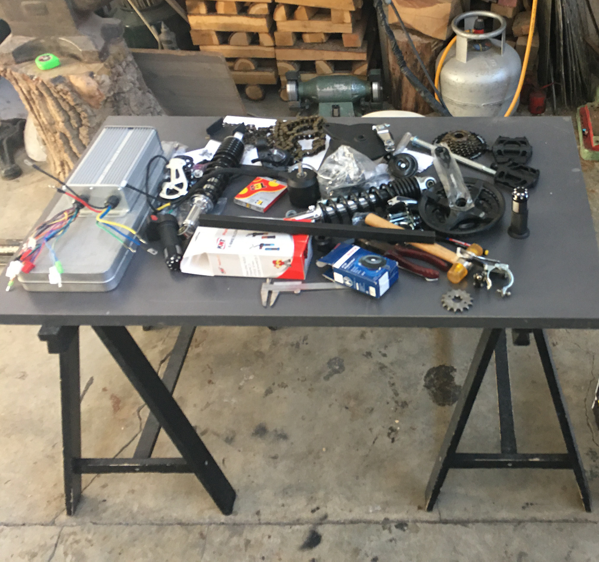
Image 6: Components required for security, control, and power systems.
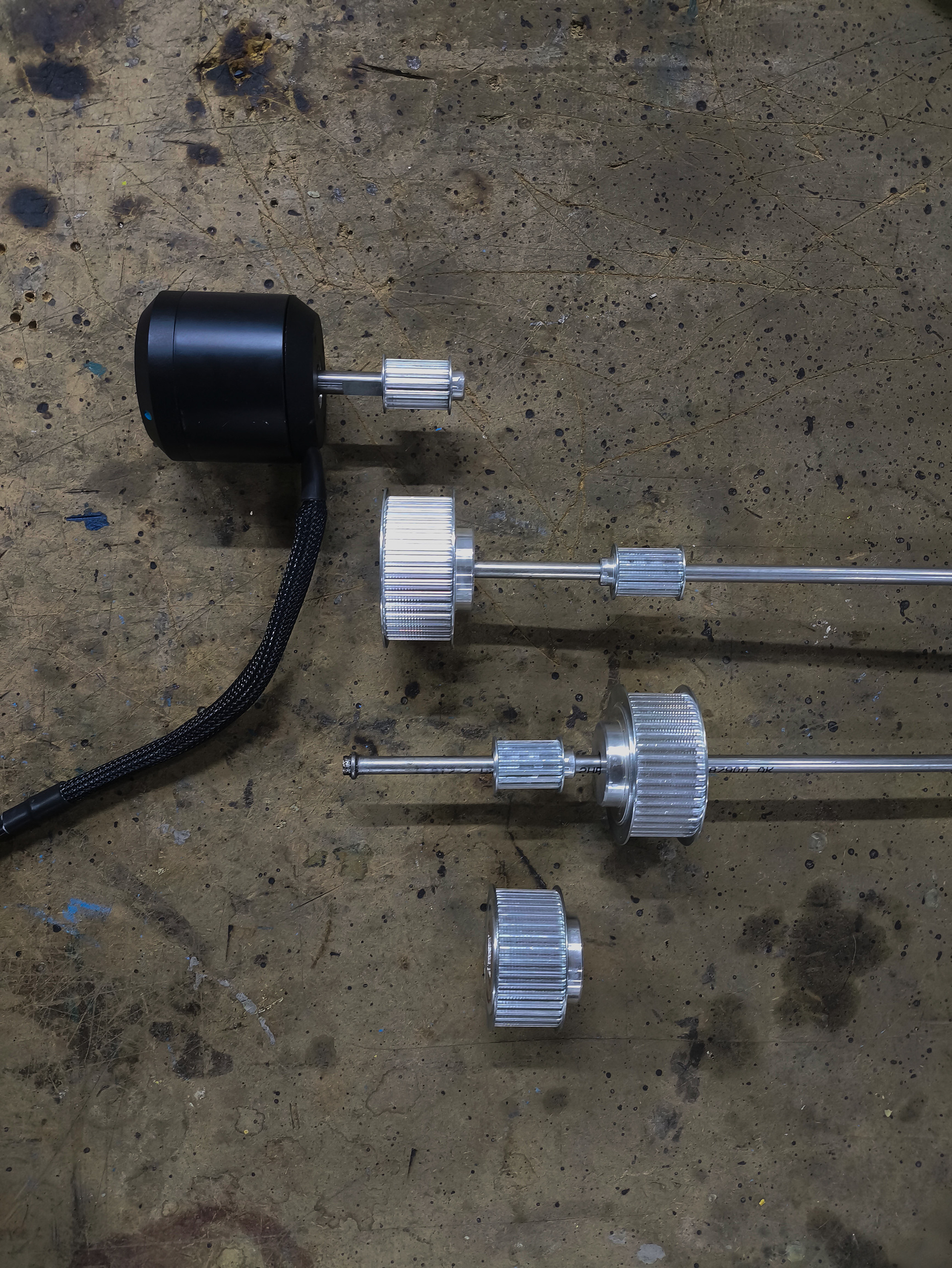
Image 7: Motor unit and pulley components.
The structural components were nearly complete. The next step was securing a power source to operate the system post-assembly.
After conducting some research, I contacted the main battery importer in Turkey. Following negotiations, we reached an agreement: 480 USD + VAT for 180 units of 32700 6Ah LiFePO4 cells. (which is a bargain)
After conducting some research, I contacted the main battery importer in Turkey. Following negotiations, we reached an agreement: 480 USD + VAT for 180 units of 32700 6Ah LiFePO4 cells. (which is a bargain)

Image 8: 180 units of 32700 LiFePO4 cells.
To operate the motor, I required a 64V power supply. Given that each cell provided 3.2V, I opted for a 20s9p configuration, resulting in a total capacity of 64V 54Ah. These cells needed to be spot-welded to ensure safety, efficiency, and reliability. However, the cost of professional spot welding was prohibitively high—so I decided to innovate.
There had been a heavy-duty spot welding machine in our workshop for as long as I could remember. It had been sitting idle, with my father even stacking stainless steel rods and bars on top of it. I figured I could repurpose it into a battery welding machine.

Image 9: Spot welding machine with stainless steel beams stacked on top.
I encountered two main obstacles. The machine had two pointed copper electrodes, one at the top and one at the bottom. When the pedal got pressed, they advanced toward each other until no space remained; with a bit more pressure, the current would be applied. Since I couldn’t clamp the batteries between them and needed the copper tips to be positioned side by side, I removed both the upper and lower copper electrodes.
Instead of using the two thick electrodes, I replaced them with one long and one short medium-thickness copper rod, shaping them into the desired form. This modification allowed the electrodes to sit side by side, resolving the issue of their original opposing positions.
However, I still couldn't activate the machine, as it required pressure to trigger the weld—and with the electrodes now aligned side by side, I could no longer apply the necessary compression.
Actually, the solution turned out to be quite simple. I wedged a wooden slab between the two arms of the machine. This prevented vertical movement, ensuring the batteries wouldn’t be crushed when the pedal was pressed—and thus, when the machine was activated.

Image 10: Modified spot welding machine, reconfigured and ready for battery spot welding.
Proud of this successful modification, I proceeded to spot weld the battery cells.
I paired the new-made battery pack with a Jikong Smart BMS—compatible with 8s to 24s configurations and capable of delivering 100A instantaneous current. I chose this model because the motor I'll be using is a BLDC with a nominal power draw of 2.2 kW and a peak power draw of 4 kW.
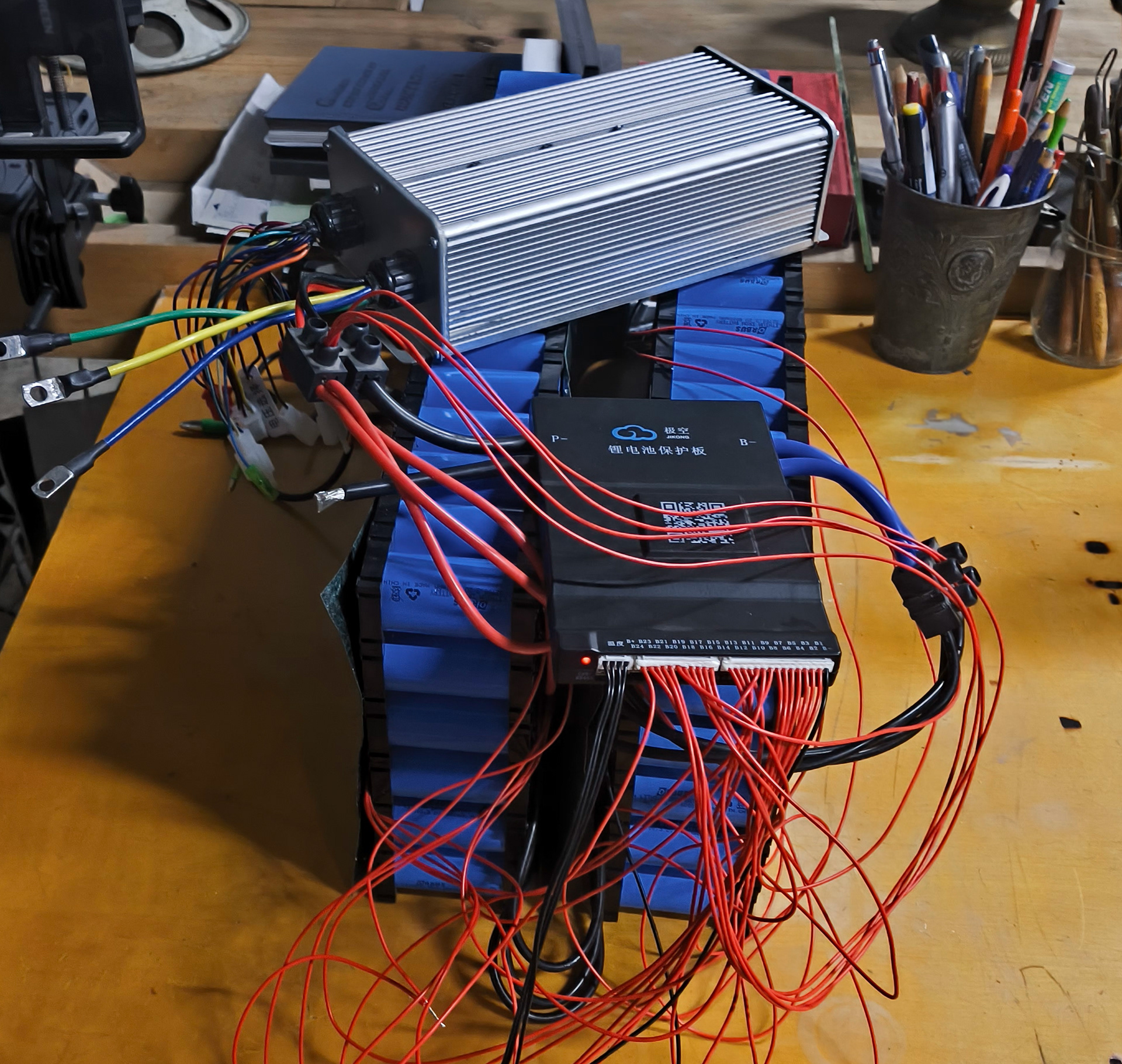
Image 11: Battery pack connected with the BLDC motor controller.
THE PROJECT IS NOT YET COMPLETE.
UPDATES WILL BE SHARED HERE!